Experience
Canon Nanotechnologies
Summer 2026
Non-disclosure and confidentiality agreements limit what I can present.
Over the summer, I conceptualized, designed (NX), and manufactured testbeds for fatigue testing of a vacuum component for a wafer lift mechanism, condensing the testing cycle of one year to two weeks. I developed the necessary software for the testbed in C++ to gather data from vacuum sensors, control the motor, and wirelessly transmit to the network, enabling live data analysis conducted using a second Python script. Both the testbed and software were designed to be modular, allowing for easy adaptation to future testing needs. Below is a picture of the testbed, which was designed to be compact and adaptable to test various versions of the vacuum component.
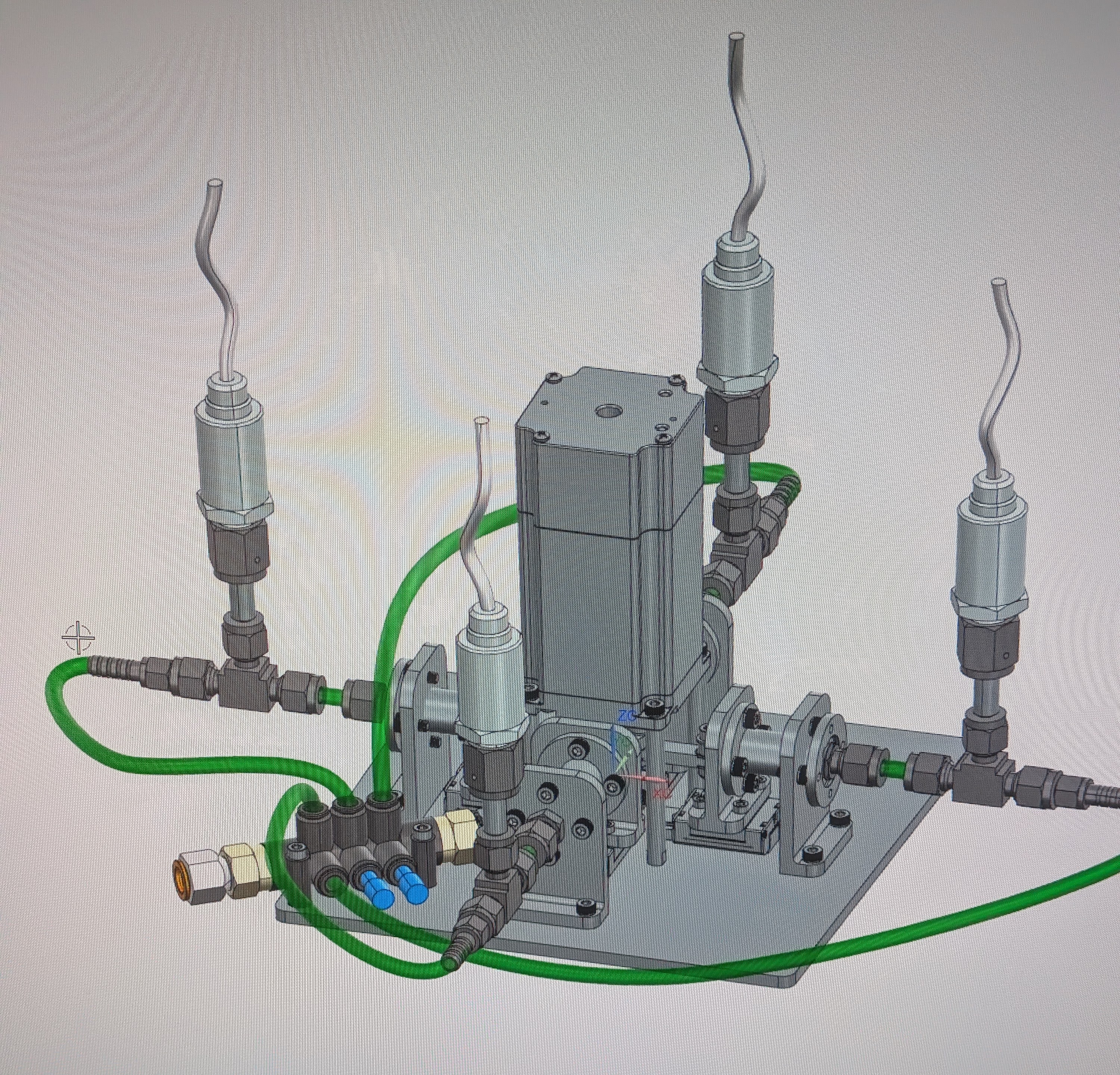
I also designed (PTC Creo) fittings for endurance testing of peristaltic pumps. However, my final project was designing and manufacturing an enclosure to test resist curing under high-power UV LEDs. The enclosure's primary purpose was to protect the user and prevent the UV light from scattering. It also permitted the test samples to be inserted at the same position over each of the four LEDs.
Robotics Automation and Design (RAD) Lab
Due to the sensitive nature of the work at the lab, I am limited in the information that I can share about the projects on which I worked.
Summer 2025
Designed, manufactured, and assembled a parasitic torque testbed to measure the effect of external cable harnessing on a space-rated robotic arm. I designed the testbed with two configurations: roll and pitch. These positions simulate the two arrangements in which the external cable harness will mount to the arm. I opted for maximum adjustability with both the rigid and moving mounts to test infinite positions. Additionally, I ensured it was easy to change between the two configurations (roll/pitch).
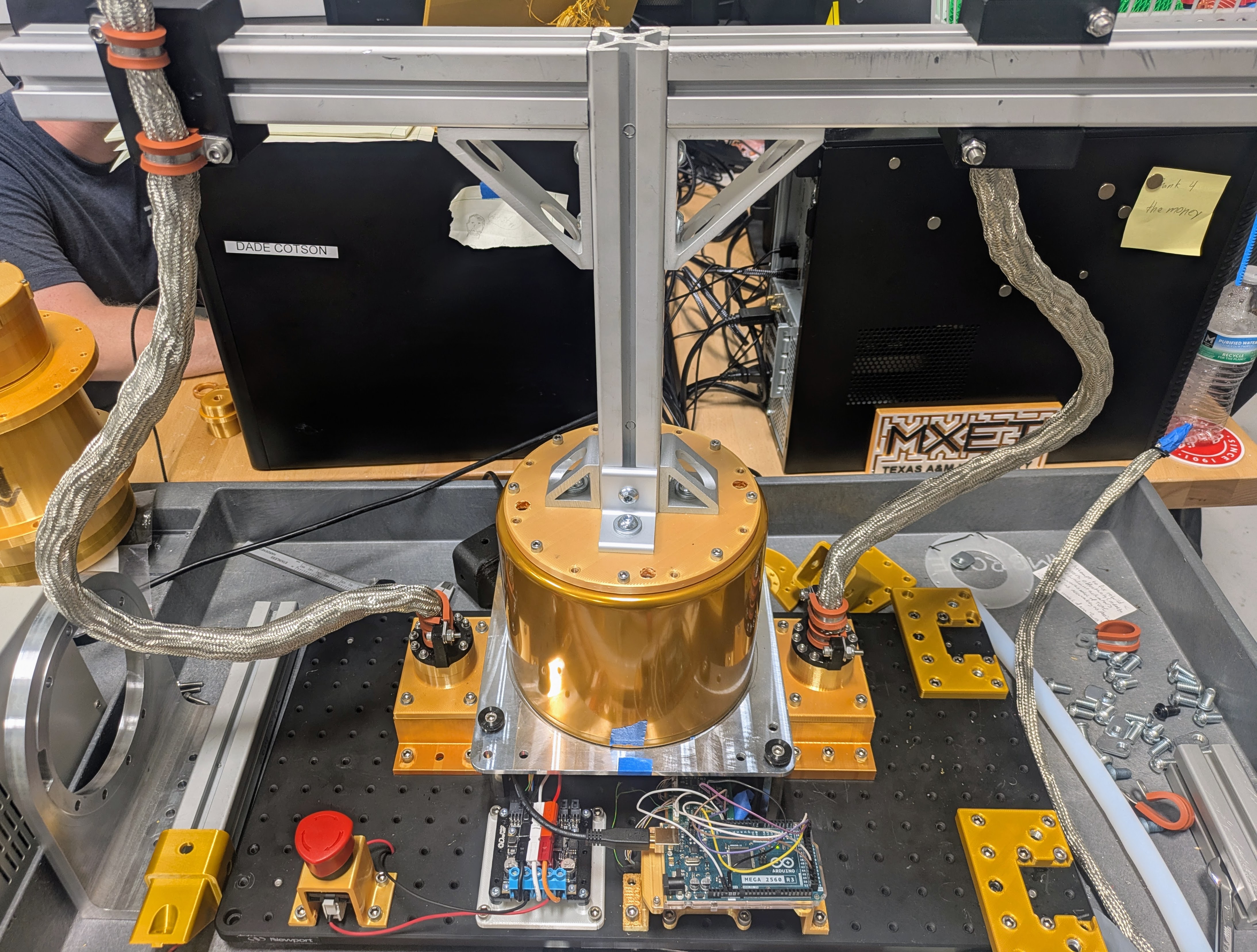
I developed a specialized enclosure to test custom motor controllers. The enclosure housed an absolute rotary encoder, which connected to the motor controller through a custom PCB. I achieved the high tolerances necessary when working with encoders. This includes concentricity between the rotor and stator as well as the proper z-height between the two components.
I produced a scale functional model of the robotic arm. This served a couple of purposes. First, it allowed for test fitting and harnessing to be done. It is difficult to do this in CAD due to the numerous complex bends present. Additionally, visualization can be difficult from a computer screen, so a physical model helped grasp the scale of components. Second, the model allowed the lab to develop assembly procedures for the arm.
Summer 2024
Developed a program to determine minimum bolt sizes for fixtures in Visual Basic for Applications (VBA). The algorithm leveraged equations from Shigley's Mechanical Engineering Design textbook and user inputs such as the thickness of the two materials, the desired preload, and the strength of the bolt. The function would return the minimum size bolt for the fixture for both Metric and Imperial hardware.
I also designed and manufactured a million-cycle testbed for wire torsion. This testbed continuously twisted the cable harness (not shown) that runs down the central bore of the actuators. The harness contains various data cables and high-current space-rated power cables. Failure of the cables was determined when the internal resistance of the power cables had doubled.
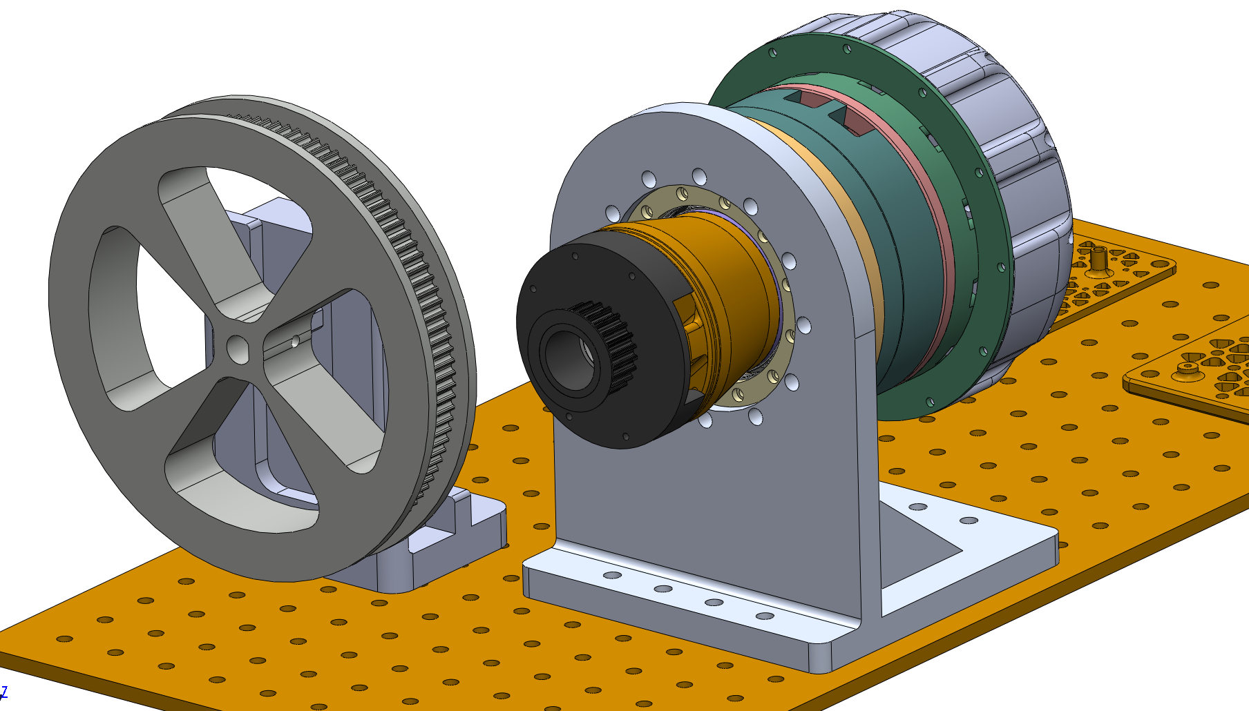
Designed space-rated Series Elastic harmonic drive oscillators. Minimizing width and length while maximizing inner bore diameter. I had to package a motor and torsion spring along with numerous encoders and bearings. Two encoders determine the delta in output between the motor and arm, which would be the deflection of the spring. With this angle, one could calculate the torque on the arm. I am unable to produce CAD models due to security reasons.